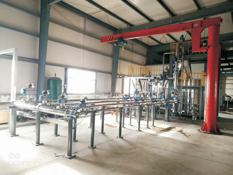
Water Flow Standard Facility LJS Type Water Flow Standard Facility Static Gravimetric Method + Static Volumetric Method + Master Meter Method
1. Description
The LJS type Water Flow Standard Facility (hereinafter referred to as the Facility) is a specialized measuring instrument required by national metrological verification regulations. It uses high-accuracy electronic scales (primary standard), standard metal measures (primary standard), and standard flow meters (secondary standard) as reference instruments. Using clean water as the calibration medium, and based on relevant national verification regulations and the calibration requirements of the meter under test (MUT), it continuously verifies, calibrates, and tests MUT flow meters within the same time intervals. It is widely used by national metrology technical supervision departments for statutory first-time and periodic verification of instruments, as well as judicial and civil arbitration. It also serves as an internal execution standard in industries such as petroleum and chemical, and is used for intelligent flow measurement testing in scientific research, metrology technical supervision, and flow meter manufacturing, offering broad standardization and applicability. To ensure the accuracy of value transfer during calibration work and to enhance the professional metrological verification knowledge of staff, this training outline is specially formulated. Personnel engaged in the facility's calibration work are expected to take it seriously, actively study, and master this course proficiently.
The facility combines multiple calibration methods: Static Gravimetric Method, Static Volumetric Method, and Master Meter Method. This multi-method complementary approach improves the facility's calibration efficiency and intelligence level, enabling online calibration or verification of standard flow meters, as well as calibration or verification of various water flow meters.
The Static Gravimetric Method uses a high-precision electronic scale as the reference. It determines the flow rate by weighing the total mass of fluid flowing into the weighing container within a set time interval and comparing it with the mass flow calculated from the MUT, thereby determining the accuracy and repeatability of the MUT. Electronic scales offer high precision; this method can achieve ±0.05% accuracy and features advantages such as constant pressure flow source, stable flow, and high measurement accuracy.
The Static Volumetric Method uses a standard metal measure as the reference. Compared to the Static Gravimetric Method, it also features constant pressure flow source, stable flow, and high measurement accuracy. However, for large flow detection, the Static Volumetric Method requires multiple standard metal measures used in combination. Manufacturing standard metal measures is relatively difficult, calibration time is longer, and maximum achievable accuracy is ±0.1%.
The Master Meter Method uses a high-precision flow meter as the reference instrument to test the MUT. Commonly used high-precision flow meters can achieve around ±0.2% measurement accuracy. For calibrating general working flow meters, this verification method is relatively simple, convenient, and cost-effective.
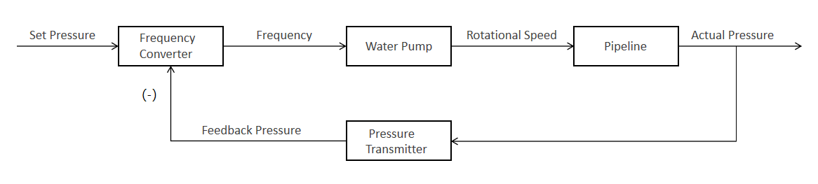
The facility's pressure stabilization method combines a stabilizing vessel and variable frequency drive (VFD) regulation. By controlling the VFD speed to regulate the pump speed, the output flow of the calibration medium is stabilized. Further stabilization by the stabilizing vessel controls flow pressure fluctuations within 0.2%. System flow regulation combines regulating valves and pump motor VFD control, meeting flow regulation demands for various pipe diameters while reducing system energy consumption.
The entire facility is controlled by computer automation supplemented by manual operation. It enables automatic control and data acquisition for the entire facility, such as electronic scale readings, standard measure readings, standard flow meter readings, MUT readings, diverter control, pressure transmitter, temperature transmitter, flow regulating valve, and VFD control and data acquisition. It can automatically perform single-point, three-point, five-point, and multi-point calibration, with functions for automatic data storage, query, printing of calibration results, and calibration certificates. The pressure stabilization method uses VFD regulation and stabilizing vessel methods based on the flow range. System flow regulation combines electric regulating valves and pump motor VFD control, meeting flow regulation needs for various diameters and reducing system energy consumption.
Users can choose a specific calibration method based on the type of meter to be calibrated, site limitations, economic conditions, etc., or integrate several methods to build the corresponding standard facility.
Facility design complies with national metrology standards, regulations, and specifications:
● JJG 164-2000 Liquid Flow Standard Facility
● JJG 643-2024 Master Meter Method Flow Standard Facility
● JJG 162-2019 Cold Potable Water Meters
● JJG 257-2007 Float Flowmeters
● JJG 640-2016 Differential Pressure Flowmeters
●JJG 667-2010 Liquid Positive Displacement Flowmeters
● JJG 1029-2007 Vortex Flowmeters
●JJG 1030-2007 Ultrasonic Flowmeters
● JJG 1033-2007 Electromagnetic Flowmeters
● JJG 1037-2008 Turbine Flowmeters
●JJG 1038-2008 Coriolis Mass Flowmeters
2. Main Content
2.1 Main Technical Parameters
2.1.1 Calibration Methods: Static Gravimetric Method + Static Volumetric Method + Master Meter Method.
2.1.2 Facility Expanded Uncertainty:
* Static Gravimetric Method: 0.05% (*k*=2) Electronic scale verification scale interval e=1/6000;
* Static Volumetric Method: 0.2% (*k*=2) Standard working measure maximum permissible error: ≤±0.5×10⁻³; if Class II standard metal measures are used, Static Volumetric Method can be 0.15% (*k*=2);
* Master Meter Method: 0.3% (*k*=2) Standard flow meter uncertainty 0.2% (*k*=2).
2.1.3 Flow Stability: ≤0.2%.
2.1.4 Flow Range: (0.02 ~ 5000) m³/h (or user-specified flow range).
2.1.5 MUT Specifications: Diameter DN4 ~ DN600 (or user-specified diameter).
2.1.6 Calibration Test Stations: Multiple groups can be set up, with parallel laid-out calibration test pipelines. Standard calibration station diameters are DN25, DN50, DN80, DN100, DN150, DN200, DN300, DN400, DN500, DN600. Other specification flow meters can be calibrated by changing pipes.
2.1.7 Types of MUTs: Turbine flow meters, vortex flow meters, electromagnetic flow meters, ultrasonic flow meters, velocity flow meters, differential pressure flow meters, liquid positive displacement flow meters, Coriolis mass flow meters, etc.
2.1.8 MUT Signals: Pulse (frequency) signal, current (4~20)mA, RS485 digital communication, no signal (direct reading), etc.
2.1.9 Calibration Medium: Clean water.
2.1.10 Working Pressure: (0.2 ~ 1.0) MPa (according to user requirements).
2.1.11 Power Supply Provided: DC (5V, 12V, 24V)/1A, AC220V/10A.
2.1.12 Control Method:
During calibration, the facility operates under automatic control. After necessary manual operations (mounting the MUT, opening/closing manual valves), the remaining calibration tasks are automatically completed by computer control.
2.1.13 Facility Materials:
Parts in contact with the test medium are made of 304 stainless steel. Other components are made of carbon steel with painted finish.
2.1.14 Facility Laboratory Space (Provided by User):
The entire facility is reasonably laid out to save space and meet laboratory requirements.
2.1.15 Facility Acceptance:
Final acceptance of the entire facility is performed by a national statutory metrology institution designated by the user. They will inspect, evaluate, and issue a verification/calibration report (certificate). This report (certificate) serves as the main acceptance document.
Other measurement units within the facility, including electronic scales, standard metal measures, standard flow meters, pressure transmitters, temperature transmitters, timers, etc., will be provided with verification/calibration reports (certificates) issued by provincial statutory metrology institutions after inspection.
2.2 Working Principle
When using the Static Gravimetric Method for calibration, the electronic scale is the reference. Within the same set time interval, the mass of calibration medium flowing through the MUT is compared to the mass measured by the electronic scale (or the mass flow calculated from the set time), determining the MUT's accuracy and repeatability.
When using the Static Volumetric Method for flow meter calibration, the MUT and the standard working measure are operated synchronously. Within the same set time interval, the volumetric flow through the MUT (or the cumulative volume calculated from the set time) is compared to the volume measured statically in the standard working measure, determining the MUT's metrological accuracy and repeatability.
When using the Master Meter Method for calibration, the calibration medium flows continuously through both the MUT and the master meter. The master meter serves as the reference, connected in series with the MUT for metrological comparison, determining the MUT's accuracy and repeatability.
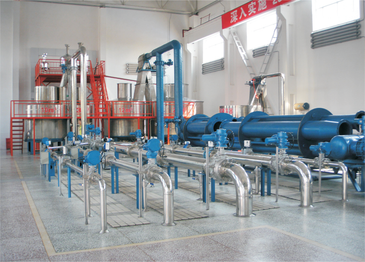
2.3 Process Flow
The test medium flows from the water tank, through the pump group, stabilizing vessel, air eliminator/filter, calibration process pipelines, standard flow meter group, flow regulating valve group, diverter, into the weighing container. After weighing by the electronic scale (or standard metal measure), it returns to the water tank. The system flow is determined by weighing the liquid flowing into the weighing container (or measuring the capacity of the standard metal measure).
Mount the MUT onto the corresponding test pipeline. Start the corresponding circulating water storage and pressure stabilization system. Adjust the regulating valve opening, medium flow velocity, and pipeline pressure to reach and stabilize at the required calibration flow rate. The test medium flows through the MUT and the flow working standard (electronic scale, standard metal measure, standard flow meter). Operate the MUT and flow working standard synchronously, compare their output flow values to determine the MUT's metrological accuracy and repeatability. The synchronously collected standard values and MUT values enter the computer system for data processing. Based on different calibration methods, the control process issues different control signals as required to bring the test medium to the flow rate of another test point. Repeat the above operation until all flow points are calibrated. Finally, calculate the calibration results based on the verification regulations, store them, and print reports and certificates.
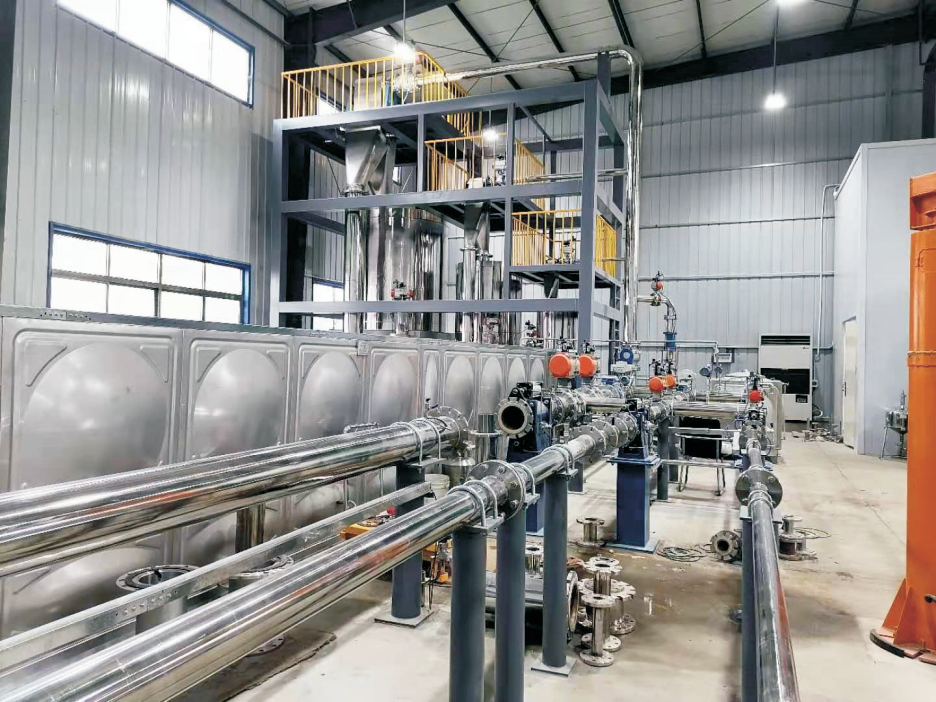
2.4 Facility Composition
2.4.1 Circulating Water Storage and Stabilization System
Composed of water tank, pump(s), VFD system, stabilizing vessel, air eliminator/filter, connecting pipes, manual gate valves, check valves, and flexible connectors, etc.
A. Power Pumps
Energy-efficient, low-vibration, low-noise centrifugal pumps are selected. They fully cover the flow range required by the facility's calibration pipelines and embody the principles of energy efficiency and optimal economy under the premise of meeting flow regulation. Multiple pumps can be used in conjunction or a single pump can be independently VFD controlled to meet the flow range of calibration pipelines.
Pump head is reasonably selected based on calculated pipeline friction and local losses from pump outlet to pipeline outlet, plus the height from tank surface to diverter nozzle and return pipe, pump suction loss, and working pressure requirements for calibration. Pump flow efficiency uses intermediate values.
Pumps are designed and manufactured using modern optimal hydraulic models, with spiral casings, horizontal suction, vertical discharge, and same inlet/outlet diameters. Direct motor connection ensures concentric shafts, stable and reliable operation, ensuring stable pump outlet pressure with minimal pressure and flow fluctuations, facilitating control and regulation.
Vibration reduction and isolation measures are applied during pump installation. Flexible connectors are installed at pump inlet/outlet to effectively reduce vibration. Slow-closing check valves are installed on outlet pipes to prevent backflow, with pressure reduction measures to eliminate water hammer. Motors operate energy-efficiently with over-current/overload protection. Positive suction head is used to avoid air entrainment and priming issues.
B. Stabilizing Vessel
The facility's pressure stabilization method is vessel stabilization + VFD regulation, used to reduce flow and pressure fluctuations during detection. It provides stable pressure for the system, eliminates high-frequency pulsation and shock waves from pumps, and removes bubbles entrained in the calibration medium. The stabilizing vessel averages, buffers, and absorbs fluid pressure pulsations, ensuring output flow pressure fluctuations remain stable within 0.2%, making the fluid in the calibration pipeline fully meet the requirements of single-phase constant flow.
Based on pump outlet fluctuation value, vessel stabilization value, and vessel inlet/outlet diameters, calculate for maximum flow to reasonably design vessel capacity, quantity, and maximum nominal pressure. Material can be 304 stainless steel or carbon steel.
The vessel has one vertical baffle, three horizontal gradient baffles with perforated grids. The vertical baffle divides the vessel into inlet and outlet chambers. The medium enters, flows up/down due to the baffle and buffer, turbulence is further reduced by horizontal baffles and the upper air cushion, then enters the outlet chamber via overflow into the pipe. This effectively absorbs and buffers high-frequency pulsation shock waves, eliminating pump-induced pulsation, acting as a pressure stabilizer and unloader. Minor system pressure changes are buffered by the automatic expansion/contraction of the air cushion space above the vessel.
Design and manufacture comply with GB150-2011 "Steel Pressure Vessels" and "Pressure Vessel Safety Technology Supervision Regulations". Flanges comply with GB150-2011 and GB/T 9112~9124-2010 "Steel Pipe Flanges". Complete safety documentation is provided (manufacturing license, quality certificate, special equipment supervision certificate, design files, installation/maintenance manuals).
Vessel accessories include pressure gauge, drain valve, spring-loaded full-lift safety valve, piping, and fittings.
C. VFD System
The facility is equipped with a one-to-one VFD system. Its functions: 1) Avoid grid impact during power frequency switching, 2) Ensure pumps always operate under VFD control for easier system flow regulation and energy saving. The system mainly consists of starter cabinet, VFD, connecting cables, etc. A single VFD controls a single pump motor (best speed range: 35Hz~50Hz). PID control is used for flow and pressure regulation. VFDs are installed in cabinets with local/emergency stop functions, manual control, and computer remote control. For safety, thermal relays are added inside cabinets for over-current/overload protection.
During operation, VFD-controlled pump motors supplement flow ranges unattainable by fixed-speed pumps. VFD operation should avoid the lower limit range to prevent dead zones and non-linear regulation. Stable flow through the MUT requires stable pressure difference across it. Regulating upstream pressure stability is key to flow stability. VFD pressure regulation uses PID algorithms; its effectiveness directly determines system performance. Implementation can be as follows:
Use a PLC as the regulator (principle shown below). Advantages: fast response, utilizes VFD manufacturer's control algorithms, improves regulation reliability.
Thermal relays in the VFD cabinet provide over-current/overload protection. VFDs also act as soft starters, protecting pumps well.
D. Air Eliminator/Filter
Considering the weighing system is an open process, the test medium can generate impurities and bubbles during detection, leading to measurement errors and potential damage to standard and MUT flow meters. Appropriately sized air eliminator/filters are installed at the stabilizing vessel outlet to separate and remove gas and impurities from the pipeline, ensuring facility performance.
Reasonably design the specifications, quantity, and maximum nominal pressure. Cylindrical shell structure with top vent valve, bottom drain valve, internal filter cartridge, air collection zone, damping plate, perforated filter screen. Material in contact with medium: 304 stainless steel; other parts: painted carbon steel.
2.4.2 Metrological Standard System
The facility's metrological standard system uses:
* High-precision electronic scales as the reference for the Gravimetric Method.
* Standard working measures as the reference for the Volumetric Method.
* Standard flow meters as the reference for the Master Meter Method.
Mainly composed of shut-off valves, flow regulating valves, diverter, weighing container, high-precision electronic scale (or standard metal measure), process piping, etc.
A. Gravimetric Weighing System (Electronic Scales)
The system accommodates calibration of MUTs at max and min flow points. Different weighing systems (scales) can be selected based on flow rate.
Example: Four weighing systems meet calibration requirements:
* Group 1: 12000kg scale, 12000L weighing container, DN300 diverter, backpressure line.
* Group 2: 3000kg scale, 3000L weighing container, DN100 diverter, backpressure line.
* Group 3: 600kg scale, 600L weighing container, DN50 diverter, backpressure line.
* Group 4: 120kg scale, 120L weighing container, DN25 diverter, backpressure line.
Scale platform consists of weighing body and frame, with sensor overload protection, standard communication interface (e.g., RS232/RS485), connectable to local display or control system, with automatic tare function.
B. Weighing Container
Weighing containers hold the test medium during Gravimetric calibration. Structure: round stainless steel container matching the scale platform size. Wall thickness meets weighing and strength requirements, ensuring no deformation over long-term use.
Example: Four containers: 12000L, 3000L, 600L, 120L. Drain time for all containers ≤40s.
Equipped with level sensor, drain valve, drain pipe, etc., with functions like liquid level monitoring, over-limit alarm, anti-splash filling, and fast draining. Design considers space and strength: round stainless steel, top flow guide grid, bottom drain pipe/valve; internal cross-shaped slot flow stabilizers welded equally to eliminate bubbles and swirling caused by flow fluctuations, providing air elimination and flow stabilization. Material: 304 stainless steel.
C. Volumetric Measurement System (Standard Working Measures)
Designed, manufactured, and selected strictly according to JJG259-2005 "Verification Regulation of Standard Metal Measures" to ensure accuracy, stability, and reliability for water flow meter calibration. Accommodates max, min, and intermediate MUT flow points. Different measurement stations (measures) can be selected based on flow rate.
Example: Three standard working measures:
* GBJ-10000L (single-height type), flow range (300~1150) m³/h.
* GBJ-3000L (combined type: 1000L+2000L), flow range (70~300) m³/h.
* GBJ-700L (combined type: 200L+500L), flow range (0.9~70) m³/h.
Measure consists of gauge neck, level tube, gauge neck scale, upper cone, cylindrical body, lower cone, drain valve, stand, and leveling components. Material in contact with liquid: 304 stainless steel.
Drain valves are pneumatic, featuring flexible operation, good sealing, and stable performance.
D. Diverter
The diverter is a key component in liquid flow facilities. It quickly switches liquid flow direction, accurately injecting liquid flowing through the MUT into the weighing container without bypass within the required time. It's a major parameter in the facility's uncertainty evaluation.
Our self-developed pneumatic open-type diverter uses an open structure, stable operation, meeting facility requirements, ensuring no splashing or flow diversion during operation. The pressure fluctuation impact on flow during diversion at max flow is a fixed value.
Diverter is paired one-to-one with scale (or measure) stations. Diverter diameter and quantity are reasonably designed. Action is light, linear axial movement, low resistance, fast action, small diversion time difference, meeting relevant verification regulations.
Technical parameters: Single-stroke diversion time ≤200ms, diversion travel time difference ≤20ms, uncertainty 0.02%, air source pressure (0.4~0.6)MPa, material in contact with medium: 304 stainless steel.
E. Standard Flow Meters (Master Meters)
Electromagnetic flow meters are primarily used as master meters, accuracy class ≤0.2, repeatability ≤0.06%. These meters also serve as standard indicators for monitoring instantaneous flow during Gravimetric calibration. By monitoring the master meter's instantaneous flow, the VFD frequency and regulating valve opening are adjusted to achieve the desired instantaneous flow in the pipeline. Standard flow velocity is typically (0.5~5) m/s, meeting max/min facility flow requirements. Master meters can be traced online via the Gravimetric method, ensuring accurate and reliable traceability while eliminating the complex labor of disassembly/reassembly for meter verification.
2.4.3 Calibration Test Pipeline System
Includes calibration test stations, manifold, standard flow meters, process piping, etc., equipped with pressure transmitters, temperature transmitters, pneumatic ball valves, electric flow regulating valves, pneumatic meter clamping devices, pipeline drain valves, pipeline vent valves, pipeline purge mechanisms, MUT workbench, pipeline supports, and other auxiliary equipment and instruments.
A. Calibration Test Stations
Based on user site conditions, multiple fixed calibration test stations are designed reasonably, arranged side-by-side. Standard station diameters: DN25, DN50, DN80, DN100, DN150, DN200, DN300, DN400, DN500, DN600. Other sizes can be calibrated by changing pipes.
B. Straight Pipe Sections
Calibration straight pipe sections designed as 20D upstream and 5D downstream of the MUT. Upstream/downstream sections have pressure/temperature tapping points meeting relevant regulation requirements, reliably sealed, facilitating MUT calibration.
Material: 304 stainless steel pipe. Outer diameter and wall thickness deviations comply with national standards.
C. Spools
The facility is equipped with spools of various calibration sizes to meet different MUT dimension requirements. Spool dimensions made per user requirements. Material: 304 stainless steel.
D. Meter Clamping Device (Expansion Joint)
The clamping device is important auxiliary equipment. This facility uses pneumatically driven double-cylinder external drive clamping devices with manual control function. This structure overcomes the drawback of undetectable internal air/water leaks in cylinder bodies. Stroke length accommodates various instruments while ensuring performance. Diameter and quantity are reasonably designed per station for holding the MUT.
Nominal pressure: 1.6MPa, standard stroke ≥200mm, air pressure (0.4~0.6)MPa, material in contact with medium: 304 stainless steel.
E. Transmitters
a. Pressure Transmitter: Accuracy class 0.075, MPE ±0.075%FS, Range (0~1.0)MPa, Output (4~20)mA, Power DC24V. Typically 3 units installed on manifolds, or user-specified per pipeline.
b. Temperature Transmitter: Accuracy class 0.2, MPE ±0.2°C, Range (0~50)°C, Output (4~20)mA, Power DC24V. Typically 3 units installed on manifolds, or user-specified per pipeline.
F. Valves
a. Pneumatic Shut-off Valves
Pipeline shut-off valves use pneumatic O-type full-bore ball valves and pneumatic butterfly valves. Powered by compressed air for quick pipeline opening/closing. Ball valve nominal pressure 1.6MPa; Butterfly valve nominal pressure 1.0MPa. Per calibration requirements, one pneumatic ball valve is set upstream of the standard flow meter, upstream of the diverter, and upstream/downstream of the MUT on each test station. One pneumatic butterfly valve is set at the drain of each weighing container. Valve core material: 304 stainless steel or full stainless steel.
b. Electric Flow Regulating Ball Valve
Monitors master meter instantaneous flow to adjust VFD frequency and valve opening, achieving required flow rate. Uses electric V-port regulating ball valves, accuracy 1%, nominal pressure 1.6MPa. One installed downstream of each master meter pipeline. Valve core material: 304 stainless steel or full stainless steel.
c. Manual Valves & Check Valves
Manual gate valves installed upstream of each pump suction port for isolation during maintenance. Check valves installed downstream of each pump discharge port to protect pumps from water hammer during normal operation. Gate valve core material: 304 or full stainless steel. Check valve material: full 304 stainless steel.
d. Manual Valves
Drain valves, vent valves, and purge mechanism control valves are set on each system pipeline. Manual control. Material: 304 stainless steel.
e. Calibration Test Cart
Movable lifting cart for transporting, stabilizing, supporting, and mounting MUTs. Specifications and quantity configured per user requirements. The stand has centering mechanism ensuring pipeline concentricity and easy MUT removal. Installation space designed to accommodate various special-size meters.
f. Pipeline Supports
Corresponding pipeline supports provided for all process pipelines. Dedicated supports provided for each diverter. Material: painted carbon steel.
2.4.4 Power Air Source System
Provides compressed air for pneumatic components in the facility, meeting normal usage requirements. Pneumatic components use first-class brands for safety, reliability, and stable performance.
A. Air Compressor
Piston-type air compressor selected based on actual needs. Advantages: high reliability, easy operation/maintenance, good dynamic balance, strong adaptability, suitable for various working conditions.
B. Air Receiver Tank
Reasonably designed volume and max nominal pressure based on number of pneumatic devices and their working pressure. Material: painted carbon steel. Equipped with pressure gauge, spring-loaded full-lift safety valve, vent valve, drain valve, piping, and fittings.
Design and manufacture comply with GB150-2011 "Steel Pressure Vessels" and "Pressure Vessel Safety Technology Supervision Regulations". Complete safety documentation provided.
2.4.5 Standard Parts
Standard parts (elbows, reducers, flanges, fasteners, gaskets, etc.) have nominal pressure ≥1.0MPa. Material: stainless steel.
2.4.6 Pipe Sections
Pipe sections use stainless steel (304) pipes, nominal pressure ≥1.0MPa. Pipes comply with relevant national standards. Practical length, quantity, and installation form configured reasonably based on actual facility layout.
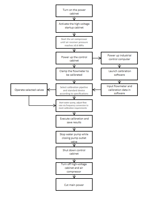
2.5 Calibration Work Procedure
2.5.1 Turn on power cabinet, VFD starter cabinet, air compressor, control cabinet, industrial computer (IPC), etc., in sequence. Confirm equipment startup and normal operation.
2.5.2 First, select the calibration pipeline diameter corresponding to the MUT diameter (calibrate different diameter meters by changing pipes). Place the MUT on the workbench tray or V-stand of the calibration test station. Adjust the hydraulic lifting mechanism of the workbench to align the center height and concentricity of the MUT with the upstream pipeline and downstream pneumatic extension (clamping) device. Then lock the hydraulic mechanism.
2.5.3 After installing the MUT, activate the pneumatic clamping device using its manual directional valve to clamp the MUT axially. Finally, secure the MUT flange connections to the pipeline flanges using matching bolts, ensuring leak-free seals. This completes MUT installation. Reverse the process for removal (Note: Before removal, open the pipeline drain valve to depressurize and drain; only remove MUT after medium is drained).
2.5.4 Start the pump corresponding to the flow range (VFD controlled; adjust pump frequency/speed during circulation to bring pipeline flow within detectable range). Slowly open selected pipeline valves. Regulate flow via the regulating valve until stable flow at the test point is achieved. At this stage, the diverter, weighing container drain valve, and return line valves are in the drain position. Simultaneously, check if equipment is running normally. If abnormal, troubleshoot and repair per relevant equipment manuals.
2.5.5 Before formal calibration, also check if all temperature/pressure instruments and scales are working. Method: Before equipment runs, check temperature instrument readings should be consistent or close; pressure instrument readings consistent or close; scales should be tared and zeroed.
2.5.6 Set calibration parameters on the software interface (refer to system software manual). Activate the diverter to switch flow direction to the test position. Fluid flows into the weighing container. After reaching the set calibration time, the diverter automatically switches. After fluid stabilizes in the container, collect scale (standard measure) data. The computer automatically records the data, then opens the drain valve to empty the container.
2.5.7 After draining and dripping for at least 30 seconds, the drain valve closes automatically, and the diverter switches automatically, starting the second run for that test point. Repeat the operation until the required number of runs for that point is completed. Proceed step-by-step to complete all flow points.
2.5.8 After calibration, turn off pumps, relevant valves, VFD starter cabinet, air compressor, power cabinet, control cabinet, and IPC in sequence.
2.5.9 Operation Flow Chart
2.6 Computer Measurement and Control System
2.6.1 System Functions
The measurement and control system uses a computer as the central control unit for data processing. Combining hardware and software, it automatically acquires and processes measurement data (temperature, pressure transmitters, standard flow meter flow, MUT flow, scales); automatically controls pumps, shut-off valves, regulating valves, VFDs, and weighing system components (diverter, drain valve); regulates pressure, temperature, and flow; switches processes; and displays, stores, and prints calibration results, completing the metrological verification process.
2.6.2 System Hardware Composition
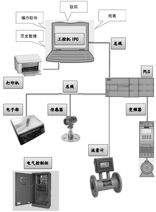
2.6.2.1 Programmable Logic Controller (PLC) & Peripherals
PLC acts as the lower-level controller. Functions include:
* Process signal handling, acquisition, conversion to parameter values for IPC (<1ms sampling time).
* Automatic process control, automatic calibration control.
* Network communication.
Uses Siemens PLC series, I/O modules, counter modules. Installed in a dedicated control cabinet complying with IEC60439, GB4942, GB50062-92. Equipped with interlock switches and alarm indicators.
Cabinet also houses peripherals (switches, fuses, relays, contactors) using domestic quality brands.
2.6.2.2 Calibration Reference Timer
Developed in-house, displays timing/counting on the main computer interface. Frequency measurement expanded uncertainty *U*=3×10⁻⁶ (*k*=2); minimum resolution ≤0.001s. Calibration interface reserved with two outputs for online timer calibration using standard frequency.
Technical specifications:
|
No. |
Item |
Parameter |
Note |
|
1 |
Crystal Oscillator 8h Stability |
≤1×10⁻⁶ |
|
|
2 |
Freq. Meas. Expanded Uncertainty |
U=3×10⁻⁶ (*k*=2) |
|
|
3 |
Timer Minimum Resolution |
0.001s |
|
2.6.2.3 Variable Frequency Drive (VFD) & Control System
Uses VFD systems to control pump speed for flow regulation. VFDs are core components, installed in VFD starter cabinets using GGD enclosure form, complying with IEC60439, GB4942, GB50062-92.
VFD system has local/emergency stop functions. Normal start/stop can be manual (local) or computer remote control.
2.6.2.4 Central Control Unit
Advantech brand Industrial PC (IPC). Main configuration:
|
No. |
Hardware Configuration |
Parameter |
Note |
|
1 |
Motherboard |
Advantech |
|
|
2 |
CPU |
I5 |
|
|
3 |
Memory |
8G |
|
|
4 |
Hard Disk |
1TB + 120G SSD |
|
|
5 |
Monitor |
24" LCD Color |
|
The IPC is the core. Using "Flow Measurement and Control Software", it receives field data from the PLC, controls system outputs, guides calibration processes, handles events, processes/calculates calibration data, presents/stores records/reports, and allows historical data query/backup.
IPC monitor, mouse, and keyboard serve as the human-machine interface (HMI).
2.6.2.5 Output Device
One A4 laser printer.
2.6.3 Software System
Consists of "Flow Measurement and Control Software", "Calibration Data Processing Software", "Communication Data Processing Program" running on the IPC; and "PLC Control Program" running on the PLC.
2.6.3.1 Software Function Flowchart
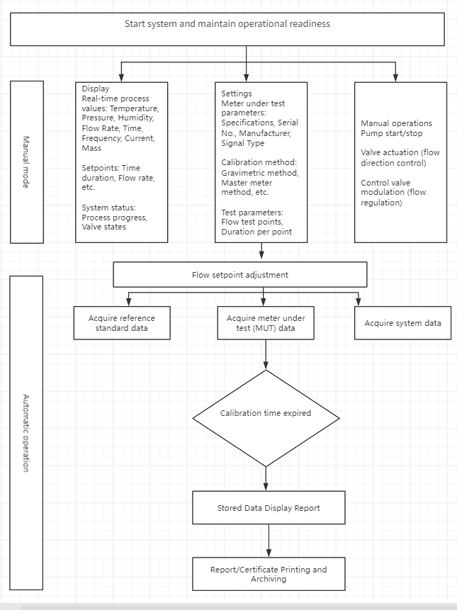
2.6.3.2 Main Software Operation Screens
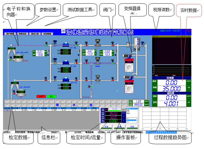
2.6.3.3 Basic Software Functions
Process Display and Operation: Dynamic process schematic diagram displays test flow status. Shows engineering parameter states in real-time. Operations comply with national standards, regulations, and procedures; accurate and reliable control.
Status Display: Displays pipeline flow field parameters (temp, pressure, velocity, flow, etc.) and equipment status in plan view.
Reporting & Historical Data Management: Generates shift, daily, monthly, annual reports for key parameters and equipment status. Reports can auto-print or be printed manually.
Message Management: Displays fault info via color changes, pop-ups, tables. Sets parameter limit alarms and equipment fault alarms.
User/Security Management: Provides multiple access levels with different operation priorities. Password levels required for field device start/stop and parameter setting to prevent misoperation.
System Management: Establishes/maintains user info. Manages users, logs login/operation history for query and security.
Save & Backup: Capability to save and backup test data and related files.
A. Control Functions
* Automatic control of calibration process.
* Pump start/stop and frequency control.
* Valve control.
* Diverter switching control.
* Container limit protection.
* Flow regulation: automatically controls regulating valve opening based on test point flow.
B. Data Acquisition Functions
* Analog signals acquired via 16-bit high-precision modules.
* Control signals handled by high-speed Boolean processor modules (independent CPU, cycle <1us) for synchronous data acquisition.
* Temperature, pressure data measurement.
* Standard flow meter flow data measurement.
* MUT flow data measurement (4-20mA, pulse, etc.).
* Scale weighing data measurement.
* Valve position signal feedback.
C. Data Processing Functions
* Processes calibration data and judges results per national standards, regulations.
* Allows segmented setting of instantaneous standard flow meter coefficients.
* Flexible setting of test points, number of runs, run times (auto per standards or user-defined).
* Stores test records in a database for query, print, modify, delete as needed.
* Automatically generates data reports and manages data.
D. Display Functions
Graphical process display for real-time equipment monitoring. Simulates field valve states, regulating valve opening, MUT signal status, flow condition, temperature, diverter direction, drain valve state, VFD frequency, etc.
E. Operation Functions
User-friendly interface with graphical operation. Control field actuators by mouse click, intuitive and convenient.
F. Wizard Function
Wizard interface guides users through the entire calibration process. Set necessary parameters/MUT info per prompts. Simple operations complete calibration after setup. Easy, fast control; easy to learn.
2.6.3.4 Specific Implementation of Key Functions
A. MUT Handling
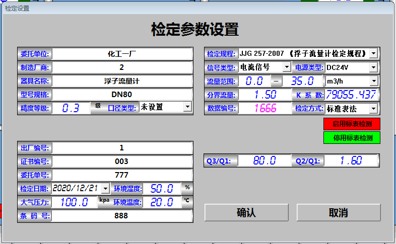
System can provide MUT power supply. MUT signals are read by PLC modules which automatically calculate accumulated flow. Mass/volume conversion, scale reading buoyancy correction, temperature/pressure correction, required data processing, and reports are automatically handled by IPC software.
As shown below, the software interface requires manual input of MUT parameters (e.g., signal type via dropdown menu: analog current, pulse, no output). After selection, the system automatically routes the signal to the correct channel.
B. Master Meter Handling
Master meter power supplied by system. Data acquired via pulse reading. Software identifies the calibration pipeline to select the relevant master meter. During calibration, the PLC automatically accumulates total pulses to ensure acquisition error ≤ ±1 pulse. Master meters can be periodically self-calibrated online using the electronic scale.
C. Temperature & Pressure Acquisition
All temp/transmitters powered by system. High conversion precision required for corrections. Uses 16-bit A/D modules with high accuracy, speed, digital filtering, and compensation.
D. Shut-off Valve & Diverter Control
Power also supplied by system. Can be controlled by clicking screen graphics/buttons or automatically per process flow. Diverter switches automatically during calibration; dedicated timer records switching time and travel time.
E. Regulating Valve Control
Control current provided by D/A module. Mainly used for flow point regulation. With stable upstream pressure, valve opening is linear to flow; regulating it achieves required test flow.
F. Scale Data Acquisition
AC220V power supplied by system. Data acquired via RS485 communication. Software can auto-select appropriate scale range based on flow point/calibration time, or operator can manually select via interface.
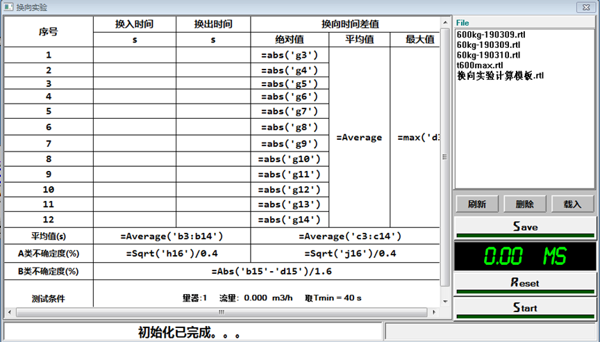
G. Diverter Test Template
Facilitates diverter time calibration within this screen, automatically generating data compliant with regulations. Data can be exported and stored in the database.
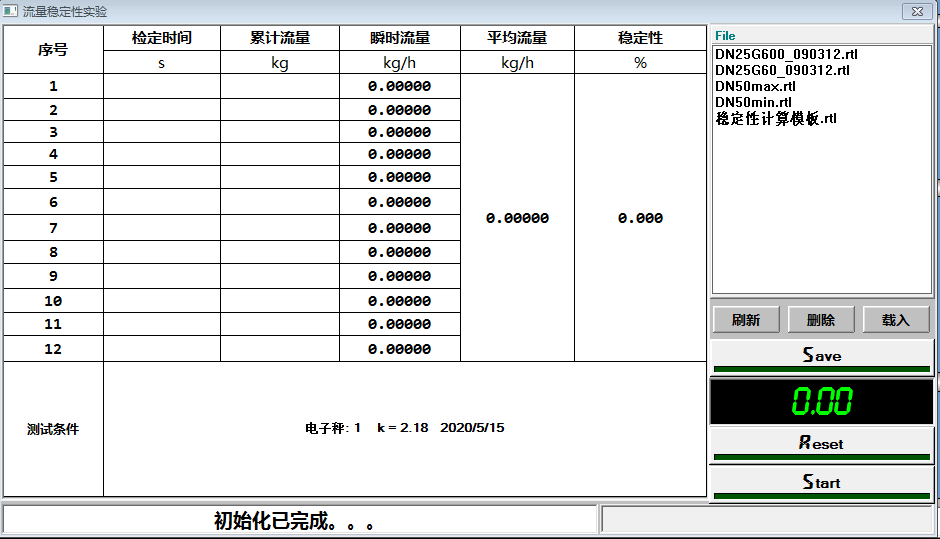
H. Stability Test Template
Facilitates flow stability calibration within this screen, automatically generating compliant data. Data can be exported and stored.
2.6.3.5 Control Program Development Software
Upper-level (IPC) control software developed using configuration software. Lower-level (PLC) control program integrated within the configuration software. Provides HMI, graphical animation of system status, intuitive control. Features good hardware compatibility and powerful functions. Developed rapidly, easy to use, friendly interface.
Calibration data processing program developed using Microsoft Office Excel VBA control code. Microsoft SQL Server database stores calibration data. Excel-based report system automatically generates reports and manages data.
Real-time data display, automatic processing, saves results and raw data for manual verification ensuring accuracy. Stores records in database for query, print, modify, delete.
Data communication service program developed using VB 6.0 SP6 for communication with scales and other instruments.
Software Upgrade & Maintenance: User-friendly, highly maintainable. Provides lifetime upgrades to adapt to changes in standards/regulations or user needs.
2.7 Maintenance Procedures
2.7.1 Key Pump Maintenance
2.7.1.1 Strictly follow pump operating procedures for start, run, stop. Keep operation records.
2.7.1.2 Check lubricant at lubrication points per shift against specifications. Strictly implement.
2.7.1.3 Check bearing temperature: ≤ ambient temp + 35°C; max roller bearing temp ≤75°C; max sleeve bearing temp ≤70°C. Check motor temperature rise per shift.
2.7.1.4 Regularly check shaft seal leakage: Packing seal ~10 drops/min; Mechanical seal: zero leakage.
2.7.1.5 Observe pump pressure, motor current (normal/stable) during operation. Listen for noise/abnormalities. Address problems promptly.
2.7.2 Control System Maintenance
2.7.2.1 Regularly clean dust from control cabinet ONLY after power is OFF.
2.7.2.2 DO NOT use facility computer for internet or unrelated programs. Regularly run virus scans and update antivirus software.
2.7.2.3 If reinstalling OS, BACK UP calibrated data first to prevent loss.
2.7.2.4 Ensure stable power supply and clear wiring for control system.
2.7.3 Pneumatic Clamping Device Maintenance
2.7.3.1 After prolonged use, lubricate extension tube with engine oil.
2.7.3.2 When working on one pipeline, CLOSE air supply valves to other pipelines to prevent other clamps being under load, affecting lifespan.
2.7.3.3 Before work, check air lines for blockages, leaks. Regularly drain accumulated water from lines.
2.7.4 Water Tank Maintenance
Regularly clean tank, replace water to prevent debris damaging pumps. Perform internal anti-corrosion/rust treatment annually or based on water quality.
2.7.5 Air Eliminator/Filter Maintenance
Important for degassing and filtering. Regularly clean internal filter element: Remove upper connecting bolts, open top flange, remove filter, clean debris from screen, replace, reassemble flange.
2.7.6 Control Room & Pump Room Maintenance
2.7.6.1 Ensure room temperature/humidity meet requirements. Keep dry and clean.
2.7.6.2 Prevent water accumulation in pump room. Clean regularly.
2.7.6.3 ALWAYS turn OFF main power before cleaning, tidying, or inspecting to avoid electric shock and injury.
Note: Maintain independent auxiliary equipment per their manuals.
2.8 Safety Operating Procedures
2.8.1 Enhance safety awareness. Increased awareness reduces accidents. Strengthening awareness, identifying hazards, knowing and implementing safety procedures are the only ways to eliminate accidents.
2.8.2 Do NOT violate rules. Violation precedes accidents; accidents result from violations. Cutting corners for convenience, speed, or effort can lead to disaster. Violations must be eliminated.
2.8.3 Truly achieve "Three No Hurts": Do not hurt yourself; Do not hurt others; Do not be hurt by others. This is fundamental to safety management.
2.8.4 Strictly comply with all site regulations. Ensure all safety hazards have designated responsible persons.
2.8.5 Operators MUST be trained before working. Must thoroughly read and understand national verification regulations, calibration specifications, and manuals BEFORE being certified to operate.
2.8.6 Calibration medium is clean water. Replace water based on turbidity to prevent pump and standard meter damage causing accidents.
2.8.7 Stabilizing vessel is a pressure vessel. DO NOT strike or modify. Keep personnel AWAY during operation.
2.8.8 When installing/removing MUT, place stably. NEVER insert fingers into connectors or feel for screw holes. Hold spacers at the sides when placing/removing.
2.8.9 After installation/commissioning, DO NOT disassemble privately to avoid damaging components.
2.8.10 DO NOT replace the computer host arbitrarily. NEVER use for internet or unrelated programs. Regularly scan for viruses and update antivirus.
2.8.11 NEVER hot-plug/disconnect any connection terminal or plug.
2.8.12 DO NOT delete operating system backup files.
2.8.13 When using compressed air, constantly check vent systems and safety valves to prevent blocked vents causing overpressure in tanks/lines.
2.8.14 Point air nozzles towards unpopulated areas, ground, or sky. NEVER point at equipment, personnel, pathways, or entrances.
2.8.15 ALWAYS turn OFF main power before cleaning, tidying, or inspecting. Prevents component loosening, electric shock, and injury.
2.8.16 Before leaving daily, operators MUST check that doors/windows and power are OFF, ensuring site safety.
2.9 Operation and Maintenance of Frequency Converter Cabinet
2.9.1 Usage: First check cabinet for abnormal sounds/smells. If OK, turn ON main control circuit switch (Power ON). Green button (Power ON) light on cabinet illuminates, fan starts, red button light also on. Now pump start/stop can be controlled via computer. Voltmeter shows ~380V, ammeter shows operating current.
2.9.2 Pump Start: Must start in VFD mode. Use computer interface to adjust VFD output to change motor speed.
2.9.3 NEVER directly set VFD frequency to maximum during operation. The inrush current is too high, potentially damaging equipment.
2.9.4 Shutdown: First stop all motors via computer. THEN press red button (Power OFF) on cabinet until all red lights OFF. Finally, turn OFF main power knife switch.
2.9.5 The manual/auto selector knob and manual VFD/line frequency start/stop button groups on the cabinet are NOT recommended for normal calibration. They are for equipment maintenance and pump debugging ONLY.
If debugging requires changing VFD settings (set to panel control mode), refer to the VFD manual.
2.9.6 Power cabinet and pump motors MUST be regularly inspected by professionals. Follow procedures for periodic checks of electrical components. Replace damaged parts promptly. Ensure normal operation. Operators MUST follow procedures. Ensure personal safety!
2.10 Equipment Repair Manual
This manual specifies the facility's maintenance cycles, content, upkeep, and troubleshooting. It serves as a reference for operators and maintenance personnel. Sources include:
(1) Equipment accompanying manuals;
(2) Relevant flow measurement regulations and specifications;
(3) Mechanical repair and process technology reference books.
2.10.1 Maintenance Cycle
Can be adjusted based on condition monitoring and equipment status.
Maintenance Cycle Table:
|
Maintenance Item |
Maintenance Type |
Minor Repair |
Major Repair |
|
Centrifugal Pump |
Cycle |
8~12 months |
12~24 months |
|
Air Compressor |
Cycle |
||
|
Process Equipment |
Cycle |
||
|
Control System |
Cycle |
2.10.2 Maintenance & Repair Content
2.10.2.1 Centrifugal Pump
A. Troubleshooting & Repair
|
Problem |
Possible Cause |
Remedy |
|
Pump does not start |
Connection interrupted |
Check wiring, correct if necessary |
|
Fuse blown |
Replace fuse |
|
|
Motor protection tripped |
Check protection settings, correct if wrong |
|
|
Motor protection not switching, control err |
Check motor protection control, correct if wrong |
|
|
Motor won't start/hard start |
Voltage/freq significantly off spec |
Improve power supply, check cable cross-section |
|
Wrong rotation direction |
Motor connection error |
Swap two phases |
|
Severe speed loss under load |
Overload |
Measure power, use larger motor or reduce load if necessary |
|
Voltage drop |
Increase cable cross-section |
|
|
Motor hums, high current |
Winding defect |
Send motor for professional repair |
|
Rotor rubbing |
||
|
Fuse blows instantly / Prot trips |
Short circuit |
Correct short circuit |
|
Motor short circuit |
Send motor for professional repair |
|
|
Wiring error |
Correct circuit |
|
|
Motor ground fault |
Send motor for professional repair |
|
|
Motor overheated (measured) |
Overload |
Measure power, use larger motor or reduce load if necessary |
|
Poor cooling |
Improve cooling airflow, clean vents, add forced fan if needed |
|
|
High ambient temp |
Stay within allowable range |
|
|
Loose connection (phase loss) |
Correct poor contact |
|
|
Fuse blown |
Find/correct cause (see above), replace fuse |
B. Equipment Maintenance: Same as Section 2.7.1
2.10.2.3 Process Equipment (Clamps, Diverter, Valves)
A. Troubleshooting & Repair
|
Problem |
Possible Cause |
Remedy |
|
|
Clamp hard to start |
Low air pressure |
Check for leaks, adjust regulator/lubricator |
|
|
Insufficient clamping force |
|||
|
Mounting position unstable |
Manual valve not fully operated |
||
|
Poor tube lubrication |
Add oil via cylinder air inlet |
||
|
Cylinder damaged |
Check & replace |
||
|
Clamp speed too fast/slow |
Low air pressure |
Adjust inlet throttle valve |
|
|
High air pressure |
Adjust inlet throttle valve |
||
|
Cylinder damaged |
Check & replace |
||
|
Diverter hard to start |
Low air pressure |
Check for leaks, adjust regulator/lubricator |
|
|
Slow switching speed |
|||
|
Switching position not reached |
Check solenoid valve, repair |
||
|
Poor inlet pipe lubrication |
Add oil via cylinder air inlet |
||
|
Cylinder damaged |
Check & replace |
||
|
Diverter time diff out of spec |
Left/right switching not synchronous |
Adjust solenoid valve outlet ports |
|
|
Photoelectric shield not positioned right |
Check & adjust shield position |
||
|
Valve hard to start |
Low air pressure |
Check for leaks, adjust regulator/lubricator |
|
|
Slow switching speed |
|||
|
Actuator cylinder leaking air |
Replace seals |
|
|
Solenoid valve not working |
Check & repair |
B. Equipment Maintenance: Per Section 2.7.3 and 2.8.13.
2.10.2.4 Control System
A. Troubleshooting & Repair
|
Problem |
Possible Cause |
Remedy |
|
Computer Fault |
Computer not working |
Check & repair |
|
Cable open or poor contact |
Check & replace cable |
|
|
Terminal open or poor contact |
Replace terminal |
|
|
System software corrupted |
Reinstall system after notifying us |
|
|
No Instrument Data |
Instrument-Control cab connection open/poor |
Check wiring & fuses Replace terminal or fuse Replace transmitter |
|
No Temp/Pressure Display |
Temp/Pressure Tx-Control cab open/poor |
|
|
Signal Power Fault |
Power module or cable faulty |
Replace module or cable |
|
Control Cab No Response |
Control cab port or cable damaged |
Replace cab terminal or cable |
- Control System Maintenance:
- Always perform regular dust removal on the control cabinet strictly when the power supply is disconnected.
- Do not use this equipment's computer for internet access or install any work-unrelated programs; perform timely virus scans and keep antivirus software updated.
- If reinstalling the system, ensure backup of calibrated data to prevent loss of verification data.
- Ensure stable power supply and unobstructed circuits for the control system.
- Regularly check signal wires on the control cabinet's I/O panel. Tighten any loose connections with a flat-head screwdriver.
- Periodically verify if switches/knobs on the control panel rotate normally. If slippage occurs, check for loose fixing screws and tighten them; replace if damaged.
- Clear static electricity from the earth leakage circuit breaker (ELCB) monthly.
2.10.2.5 Test Run & Acceptance
A. Pre-Test Preparation: Confirm repair completion, quality, records; site clean; instruments/control/interlocks debugged; oil system filled; air system vented/drained; electrical system repaired/powered; tools ready.
B. Test Run: No-load test; confirm oil/water/air/electric/instrument systems normal; run 72 hours problem-free before acceptance; acceptance signed by relevant personnel.