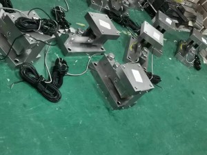
Today we will share how to judge whether the sensor is operating normally.
First of all, we need to know under what circumstances we need to judge the operation of the sensor. There are two points as follows:
1. The weight displayed by the weighing indicator does not match the actual weight, and there is a big difference.
When we use standard weights to test the accuracy of the scale, if we find that the weight displayed by the indicator is quite different from the weight of the test weight, and the zero point and range of the scale cannot be changed by the calibration, then we must consider whether the sensor is It's not broken. In our actual work, we have encountered such a situation: a package weighing scale, the package weight of a package of feed is 20KG (the package weight can be set as needed), but when the package weight is checked with an electronic scale , Either more or less, which is quite different from the target volume of 20KG.
2. The alarm code "OL" appears on the indicator.
This code means overweight. If the indicator frequently reports this code, check whether the sensor is working well
How to judge whether the sensor is operating normally
Measuring resistance (Disconnect indicator)
(1) It would be much easier if there is a sensor manual. First use a multimeter to measure the input and output resistance of the sensor, and then compare it with the manual. If there is a big difference, it will be broken.
(2) If there is no manual, then measure the input resistance, which is the resistance between EXC+ and EXC-; the output resistance, which is the resistance between SIG+ and SIG-; the bridge resistance, which is EXC+ to SIG+, EXC+ to SIG-, The resistance between EXC- to SIG+, EXC- to SIG-. The input resistance, output resistance, and bridge resistance should satisfy the following relationship:
"1", input resistance>output resistance>bridge resistance
"2", the bridge resistance is equal or equal to each other.
Measuring voltage (the indicator is energized)
First, use a multimeter to measure the voltage between the EXC+ and EXC- terminals of the indicator. This is the excitation voltage of the sensor. There are DC5V and DC10V. Here we take DC5V as an example.
The output sensitivity of the sensors we touched is generally 2 mv/V, that is, the output signal of the sensor corresponds to a linear relationship of 2 mv for every 1V excitation voltage.
When there is no load, use a multimeter to measure the mv number between the SIG+ and SIG- lines. If it is about 1-2mv, it means that it is correct; if the mv number is particularly large, it means that the sensor is damaged.
When loading, use the multimeter mv file to measure the mv number between the SIG+ and SIG- wires. It will increase in proportion to the loaded weight, and the maximum is 5V (excitation voltage) * 2 mv/V (sensitivity) = about 10mv, if not , It means that the sensor is damaged.
1. Can not exceed the range
Frequent over-range will cause irreversible damage to the elastic body and strain gauge inside the sensor.
2. Electric welding
(1) Disconnect the signal cable from the weighing display controller;
(2) The ground wire for electric welding must be set near the welded part, and the sensor must not be part of the electric welding circuit.
3. Insulation of sensor cable
The insulation of the sensor cable refers to the resistance between EXC+, EXC-, SEN+, SEN-, SIG+, SIG- and the shielding ground wire SHIELD. When measuring, use a multimeter resistance file. The gear is selected at 20M, and the measured value should be infinite. If it is not, the sensor is damaged.
Post time: Dec-27-2021


