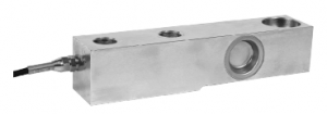
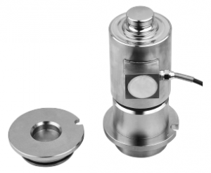
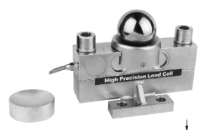
We all know that the core component of an electronic scale is theload cell, which is called the "heart" of an electronic scale. It can be said that the accuracy and sensitivity of the sensor directly determine the performance of the electronic scale. So how do we choose a load cell? For our general users, many parameters of the load cell (such as nonlinearity, hysteresis, creep, temperature compensation range, insulation resistance, etc.) really make us overwhelmed. Let's take a look at the characteristics of the electronic scale sensor about the main technical parameters.
(1) Rated load: the maximum axial load that the sensor can measure within the specified technical index range. But in actual use, generally only 2/3~1/3 of the rated range is used.
(2) Allowable load (or safe overload): the maximum axial load allowed by the load cell. Overwork is allowed within a certain range. Generally 120%~150%.
(3) Limit load (or limit overload): the maximum axial load that the electronic scale sensor can bear without making it lose its working ability. This means that the sensor will be damaged when the work exceeds this value.
(4) Sensitivity: The ratio of the output increment to the applied load increment. Typically mV of rated output per 1V of input.
(5) Nonlinearity: This is a parameter that characterizes the accuracy of the corresponding relationship between the voltage signal output by the electronic scale sensor and the load.
(6) Repeatability: Repeatability indicates whether the output value of the sensor can be repeated and consistent when the same load is applied repeatedly under the same conditions. This feature is more important and can better reflect the quality of the sensor. The description of the repeatability error in the national standard: the repeatability error can be measured with the nonlinearity at the same time as the maximum difference (mv) between the actual output signal values measured three times on the same test point.
(7) Lag: The popular meaning of hysteresis is: when the load is applied step by step and then unloaded in turn, corresponding to each load, ideally there should be the same reading, but in fact it is consistent, the degree of inconsistency is calculated by the hysteresis error. an indicator to represent. The hysteresis error is calculated in the national standard as follows: the maximum difference (mv) between the arithmetic mean of the actual output signal value of the three strokes and the arithmetic mean of the actual output signal value of the three upstrokes at the same test point.
(8) Creep and creep recovery: The creep error of the sensor is required to be checked from two aspects: one is creep: the rated load is applied without impact for 5-10 seconds, and 5-10 seconds after loading. Take readings, then record the output values sequentially at regular intervals over a 30-minute period. The second is creep recovery: remove the rated load as soon as possible (within 5-10 seconds), immediately read within 5-10 seconds after unloading, and then record the output value at certain time intervals within 30 minutes.
(9) Allowable use temperature: specifies the applicable occasions for this load cell. For example, the normal temperature sensor is generally marked as: -20℃ - +70℃. High temperature sensors are marked as: -40°C - 250°C.
(10) Temperature compensation range: This indicates that the sensor has been compensated within such a temperature range during production. For example, normal temperature sensors are generally marked as -10°C - +55°C.
(11) Insulation resistance: the insulation resistance value between the circuit part of the sensor and the elastic beam, the bigger the better, the size of the insulation resistance will affect the performance of the sensor. When the insulation resistance is lower than a certain value, the bridge will not work properly.
Post time: Jun-10-2022


